Note
Go to the end to download the full example code.
.geo File: Rectangle#
This example demonstrates the procedure for generating a structured mesh for rectangle. Note that Phasefieldx can import external meshes in the .msh format. This can be achieved by using Gmsh.
Files with the .geo format define both the geometry and the mesh parameters, such as element types and sizes. Gmsh can then generate the mesh based on the input from these .geo files.
Below is an example of the .geo file used for mesh generation.
.geo file#
// -----------------------------------------------------------------------------
//
//  Gmsh GEO
//
//  Mesh size fields
//
// -----------------------------------------------------------------------------

//Use the following line to generate the mesh
//gmsh file.geo  -2 -o mesh.msh

// Parameters
Lx = 10;  // Length of the rectangle in x-direction
Ly = 5;   // Length of the rectangle in y-direction
ndiv_x = 10; // Number of divisions along the x-direction
ndiv_y = 5;  // Number of divisions along the y-direction


// ------------------------------------------------------
// ------------------------------------------------------
// A)Geometry Definition: 1)Points
//                        2)Lines
//                        3)Curve
//                        4)Surface

// ------------------------------------------------------
// A1)Points Definitions:
//
//           4*-------------------------------*3   -
//            |                               |    |
//            |                               |    |
//            |               * (0,0)         |    |    Ly
//            |                               |    |
//            |                               |    |
//            *-------------------------------*    -
//            1                               2
//    |Y      |---------------Lx--------------|
//    |
//    ---X


//          -----Coordinates--
//Points:   ----X,------Y,---Z,
Point(1) = {-Lx/2,  -Ly/2,   0, 1.0};
Point(2) = { Lx/2,  -Ly/2,   0, 1.0};
Point(3) = { Lx/2,   Ly/2,   0, 1.0};
Point(4) = {-Lx/2,   Ly/2,   0, 1.0};

// ------------------------------------------------------
// A2)Lines Definition
//
//                            <-L3
//            *-------------------------------*
//            |                               |
//            |                               | ^
//          L4|                               | L2
//          \/|                               |
//            |                               |
//            *-------------------------------*
//                  L1->

Line(1) = {1, 2};  // Bottom line
Line(2) = {2, 3};  // Right line
Line(3) = {3, 4};  // Top line
Line(4) = {4, 1};  // Left line


// ------------------------------------------------------
// A3)Curve Definition
//
//            *---------------<---------------*
//            |                               |
//            |                               |
//           \/                               /\
//            |                               |
//            |                               |
//            *--------------->---------------*
//

Line Loop(1) = {1, 2, 3, 4};


// ------------------------------------------------------
// A4)Surface Definition
//
//            *-------------------------------*
//            |                               |
//            |                               |
//            |      S1                       |
//            |                               |
//            |                               |
//            *-------------------------------*
//

Plane Surface(1) = {1};

// Transfinite Surface and Recombination
Transfinite Surface {1};
Recombine Surface {1};

// Set transfinite lines for structured mesh with different divisions
Transfinite Line {1} = ndiv_x + 1;
Transfinite Line {2} = ndiv_y + 1;
Transfinite Line {3} = ndiv_x + 1;
Transfinite Line {4} = ndiv_y + 1;


// ------------------------------------------------------
// B4)Extrude Mesh (for 3D)

//      {X, Y,    Z} Surface
// Extrude {0, 0, 5.0}{Surface{1}; Layers{1};Recombine;}

// ------------------------------------------------------
// B5)Mesh Algorithm
Geometry.Tolerance = 1e-12;
For more information about Gmsh and the .geo file format, please refer to the official Gmsh website.
To generate the mesh in the .msh format from the terminal, use the following Gmsh command:
Here, -3 specifies that the mesh is 3-dimensional, and -o mesh.msh tells Gmsh to save the mesh to a file named mesh.msh with the .msh extension.
Alternatively, you can generate the mesh using the Gmsh Python API, which allows for programmatic mesh generation within Python scripts.
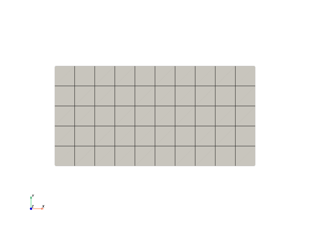
Mesh Visualization#
The purpose of this code is to visualize the mesh. The mesh is generated from the .geo file and saved as output_mesh_for_view.vtu. It is then loaded and visualized using PyVista.
import os
import gmsh
import pyvista as pv

folder = "9104_Structured"
Initialize Gmsh
gmsh.initialize()
Open the .geo file
geo_file = os.path.join(folder, "file.geo")
gmsh.open(geo_file)
Generate the mesh (2D example, for 3D use generate(3))
gmsh.model.mesh.generate(2)
Write the mesh to a .vtk file for visualization Note that the input mesh file for the phasefieldx simulation should have the .msh extension. Use “output_mesh_for_view.msh” to generate the mesh for the simulation input. In this case, the mesh is saved in .vtk format to facilitate visualization with PyVista.
vtu_file = os.path.join(folder, "output_mesh_for_view.vtk")
gmsh.write(vtu_file)
Finalize Gmsh
gmsh.finalize()

print(f"Mesh successfully written to {vtu_file}")


file_vtu = pv.read(vtu_file)
file_vtu.plot(cpos='xy', color='white', show_edges=True)
Mesh successfully written to 9104_Structured/output_mesh_for_view.vtk
Total running time of the script: (0 minutes 0.185 seconds)