Note
Go to the end to download the full example code.
.geo File: Symmetry ASTM Standard E-399-72#
This example illustrates the process of generating a mesh for an ASTM Standard E-399-72 specimen, as described in cite{TADA}, considering only the symmetric half of the geometry. Note that Phasefieldx can import external meshes in the .msh format. This can be achieved by using Gmsh.
Files with the .geo format define both the geometry and the mesh parameters, such as element types and sizes. Gmsh can then generate the mesh based on the input from these .geo files.
Below is an example of the .geo file used for mesh generation.
.geo file#
// -----------------------------------------------------------------------------
//
//  Gmsh GEO: Symmetry ASTM Standard E-399-72
//
// -----------------------------------------------------------------------------
//
// Symmetry ASTM Standard E-399-72
//
//
//gmsh file.geo  -3 -o mesh.msh
//
//   *-------------------------*
//   |    ---                  |
//   |  /     \                |
//   | |   *   |               |
//   |  \     /                |
//   |    ---                  |
//   |                         |
//    ----------------         |
//   |                         |
//   |    ---                  |
//   |  /     \                |
//   | |   *   |               |
//   |  \     /                |
//   |    ---                  |
//   *-------------------------*
//
//
//   *-------------------------*
//   |    ---                  |
//   |  /     \                |
//   | |   *   |               |
//   |  \     /                |
//   |    ---                  |
//   |                         |
//   *-------------------------*
//
//

h      = 0.05;  //mesh size
hcrack = 0.01; //mesh size near crack
SetFactory("OpenCASCADE");

// ------------------------------------------------------
// ------------------------------------------------------
// A)Geometry Definition: 1)Points
//                        2)Lines
//                        3)Curve
//                        4)Surface

// ------------------------------------------------------
// A1)Points Definitions:
//
//         P4*----------*P3
//           |          |
//           |          |
//         P1*----------*P2
//
//    |Y
//    |
//    ---X
// Z /
//

//           -----Coordinates--
//Points:    -----X,------Y,---Z,
Point(1)   ={ -0.25,    0.0,   0,  h};
Point(2)   ={   1.0,    0.0,   0,  h};
Point(3)   ={   1.0,    0.6,   0,  h};
Point(4)   ={ -0.25,    0.6,   0,  h};


// ------------------------------------------------------
// A2)Lines Definition
//
//            <-L3
//        *----------*
//     |L4|          |
//        |          | ^L2
//        |          |
//        *----------*
//           L1->

Line(1) = {1, 2};  //L1:from P1 to P2: P1*--L1-->*P2
Line(2) = {2, 3};
Line(3) = {3, 4};
Line(4) = {4, 1};


//        *----------------*
//        |  / - \         |
//        |  |   |         |
//        |  \ - /         |
//        *     -----------|
//        |  / - \         |
//        |  |   |         |
//        |  \ - /         |
//        *----------------*

Circle(39) = {0.0,  0.275, 0.0, 0.125, 0.0,   Pi};
Circle(40) = {0.0,  0.275, 0.0, 0.125,  Pi, 2*Pi};


// ------------------------------------------------------
// A3)Curve Definition
//
//
//        *----<-----*
//        |          |
//        *  \       |
//            *      ^ Curve 5
//        *  /       |
//        |          |
//        *----->----*
//

Curve Loop(5) = {1,2,3,4};  //C5: through lines L1,L2,...,L7
Curve Loop(6) = {39, 40};


// ------------------------------------------------------
// A4)Surface Definition
//
//

Plane Surface(6) = {5, 6};  // Subtract circle loops 39 and 40 from the main surface 5
//Recombine Surface {6};


// ------------------------------------------------------
// ------------------------------------------------------
// B)Mesh Generation: 1)Mesh size Box1
//                    2)Mesh size Box2
//                    3)Mesh min(Box1,Box2)
//                    3)Extrude Mesh
//                    4)Mesh Algorithm


// ------------------------------------------------------
// B1) Mesh size Box1
//
//        *----------------*
//        |  / - \         |
//        |  |   | (Field[6])
//        |  \ - /         |
//         -----------     |
//        |                |
//        |                |
//        |                |
//        *----------------*

Field[6]      = Ball;
Field[6].VIn  = hcrack;
Field[6].VOut = h;

Field[6].XCenter = 0.0;        // X-coordinate of the center of the circle
Field[6].YCenter = 0.275;    // Y-coordinate of the center of the circle
Field[6].ZCenter = 0.0;        // Z-coordinate of the center of the circle (for 2D, keep it zero)
Field[6].Radius  = 0.145;    // Radius of the circle


// ------------------------------------------------------
// B3) Mesh size Box2
//


Field[8]      =    Box;
Field[8].VIn  = hcrack;
Field[8].VOut =      h;

Field[8].XMin =  0.45;
Field[8].XMax =   1.0;
Field[8].YMin =   0.0;
Field[8].YMax =   0.1;

// ------------------------------------------------------
// B3) Mesh min(Box1,Box2)
Field[9] = Min;
Field[9].FieldsList = {6,8};
Background Field = 9;


// ------------------------------------------------------
// B4)Extrude Mesh

//     {X, Y,    Z}    Surface
Extrude{0, 0,  0.5}{Surface{6}; Layers{{2},{1}}; Recombine;}


// ------------------------------------------------------
// B5)Mesh Algorithm
Geometry.Tolerance = 1e-12;
Mesh.SaveAll = 1;

// ------------------------------------------------------
// Physical groups definition
//
Physical Volume("speciment", 67) = {1};
For more information about Gmsh and the .geo file format, please refer to the official Gmsh website.
To generate the mesh in the .msh format from the terminal, use the following Gmsh command:
Here, -3 specifies that the mesh is 3-dimensional, and -o mesh.msh tells Gmsh to save the mesh to a file named mesh.msh with the .msh extension.
Alternatively, you can generate the mesh using the Gmsh Python API, which allows for programmatic mesh generation within Python scripts.
The Stress Analysis of Cracks Handbook, Third Edition. Tada, Hiroshi; Paris, Paul C. https://doi.org/10.1115/1.801535
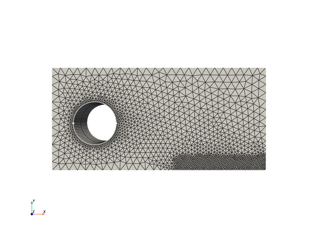
Mesh Visualization#
The purpose of this code is to visualize the mesh. The mesh is generated from the .geo file and saved as output_mesh_for_view.vtu. It is then loaded and visualized using PyVista.
import os
import gmsh
import pyvista as pv

folder = "9110_Symmetry_ASTM_Standard_E_399_72"
Initialize Gmsh
gmsh.initialize()
Open the .geo file
geo_file = os.path.join(folder, "file.geo")
gmsh.open(geo_file)
Generate the mesh (2D example, for 3D use generate(3))
gmsh.model.mesh.generate(3)
Write the mesh to a .vtk file for visualization Note that the input mesh file for the phasefieldx simulation should have the .msh extension. Use “output_mesh_for_view.msh” to generate the mesh for the simulation input. In this case, the mesh is saved in .vtk format to facilitate visualization with PyVista.
vtu_file = os.path.join(folder, "output_mesh_for_view.vtk")
gmsh.write(vtu_file)
Finalize Gmsh
gmsh.finalize()

print(f"Mesh successfully written to {vtu_file}")


file_vtu = pv.read(vtu_file)
file_vtu.plot(cpos='xy', color='white', show_edges=True)
Mesh successfully written to 9110_Symmetry_ASTM_Standard_E_399_72/output_mesh_for_view.vtk
Total running time of the script: (0 minutes 0.429 seconds)